
If you have been in the Architectural Millwork or Custom Cabinet business for any length of time, you are probably familiar with the Shop Drawing Review Process. But what if you are a new Draftsman (or perhaps a newly promoted Lead-Draftsman) – would you know what is expected if asked to Review Millwork Shop Drawings?
The Shop Drawing Review Process can vary from one Cabinet Shop to another but the basic purpose is always the same. Shop Drawings must be checked for Technical Accuracy against the reference drawings and they must also be checked for compliance with Internal Drafting Standards.
In this blog post I’m going to walk you through our process here at Superior Shop Drawings. It consists of 3 Steps (perhaps “stages” is a better word) and is designed to provide our customers with organized, consistent drawings that are technically accurate.
Step 1: CAD File Review
The first step in our Shop Drawing Review Process begins with the AutoCAD File. Before we dive into Plan, Elevation, or Section Views – we want to make sure that the drawing file itself is clean and well organized.
This is critical simply because of the type of business we run. As an Outsource Drafting Service – we supply our customers with the AutoCAD File as well as all of the associated External References and Support Files for a given project. If the CAD File was in disarray and difficult to use, it would be an embarrassment.
To ensure that our CAD File goes beyond the expectations of our customers, we have developed a system of checks for the CAD portion of the review.
By comparison, this stage of the review process is the quickest. It allows us to skim the drawing to look for things that should stand out.
Was the Correct Dimension and Multi-Leader Style Used?
When we start any project – it begins with an AutoCAD Template. This template is pre-set with all of the necessary Dimension and Multi-Leader Styles. While this gets us off to a great start, it doesn’t always stop weird things from happening.
The biggest culprit for issues with Dimension and Multi-Leader Styles generally stems from Copy & Pasting from old drawings. In some instances – Styles will be attached to what you have copied and will become embedded when pasting into your current drawing. When this happens, it is easy to accidentally select the wrong style and begin using it.
A quick scan of the drawing will ensure that a rouge Dimension or Multi-Leader Style wasn’t introduced somewhere along the way. If something odd has been introduced, we want to make sure that we identify and correct the issue.

Was the Correct Text Style Used?
As I mentioned earlier, when we start any new project we have an AutoCAD template that has many things pre-set for us. One of those presets is the Text Styles that we are going to use in any given project. Different Styles are used for different things such as – Dimensions, Multi-Leaders, Notations, and RFI’s.
Because our Internal Procedures Manual and Drafting Standards stipulate which Text Style is used in each situation – we want to take a look around to ensure that everything is as it should be.
If your Dimension and Multi-Leader Styles are set up correctly from the start, the only thing you will need to check during this review process is notations. A quick scan of your drawing should show you any notations that look out of place.

Do Elements Contain Multiple Annotative Scales?
Have you ever opened up an AutoCAD File, clicked on a dimension, and been greeted by a jumbled mess of annotative scales? This is a problem that is often caused by enabling “Automatically Add Scales to Annotative Objects”. While this feature has certain benefits – it can turn an otherwise clean drawing into a messy one if various annotative scales are being used throughout the project.
The biggest hurdle associated with this issue is the way in which extra Annotative Scales must be removed. Fortunately, Steve wrote a Blog Post detailing his Top 5 Favorite LISP Files. One of those LISP Files deals specifically with changing or removing multiple annotative objects – which makes correcting this problem a snap.

Are Lines Straight and Corners Square?
While walls are rarely straight and square in the field – we feel that they should be drawn that way unless field conditions dictate otherwise. This ensures that, during the drawing process, Counter Tops, Cabinets, and other Millwork Items do not take on odd shapes.
This is easy to achieve by using Ortho paired with the Polylines and Rectangle Commands. This ensures that your walls are straight and will not create a compounding problem when lines are offset to create millwork items.
To check for straight lines and square corners, we like to strike Construction Lines. Since the Construction Line will always be straight (either horizontal or vertical) the object under it should become hidden. If it peeks out from the Construction Line, we know that something isn’t quite right.

Have Rogue Layers been Added?
Have you ever worked on a set of drawings and realized that you needed a piece of specialty hardware? The more you look at the piece of hardware, the more familiar it looks. Then it dawns on you that you have drawn this before. After a little research you track down the hardware in an older drawing and, to save time, you do what most drafters do – you Copy & Paste.
We find that this is the biggest culprit for rogue items finding their way into active drawings. Any Layers, Dimension Styles, or Multi-Leaders Styles that are associated with the original drawing will be pasted along with the geometry.
Fortunately, if you keep a working list of Layers, spotting these rouge layers is a simple process. All you have to do is open up the Layer Manager and look for something that looks as though it doesn’t belong.
Removing any unwanted layers can be as simple as using the purge command. If a layer is embedded and in-use somewhere, things can get a little tricky. The nuclear option is to use the Delete Layer Command – be warned that you may lose lines going this route.

Have Rogue Dimension or Multi-Leader Styles been Added?
As we’ve said already, the biggest culprit for unwanted junk in your AutoCAD File usually stems from a hasty Copy & Paste. This includes unwanted Layers, Dimension Styles, and Multi-Leader Styles.
Unlike Rouge Layers, that can become a real headache, Dimension and Multi-Leader Styles are generally easy to remove. They can be discovered by opening up the appropriate Style Manager and looking to see if anything has been added.
If there is something listed that looks out of place – you can usually remove it from inside the Style Manager or Purge it away.

Have Old Xrefs been Removed?
A common practice among Millwork Drafters is to use the Architectural Drawings as a PDF Underlay. The purists in the audience may find this practice blasphemous but there are pros and cons to drawing over top of the Architecturals.
Not only can the Architectural Drawings be used as an Underlay – Photos can be inserted into the drawing and used as a guide for Matching Custom Molding.
Somewhere along the way, you will wind up inserting an object as an External Reference inside of your working drawing. More often than not, the object will be deleted and forgotten about when you are finished. The issue arises if you forgot to remove the External Reference through the Reference Manager.
A simple check of the Reference Manager will show any issues that need to be address. If the issue is not corrected – the next person to open the drawing may get an error that a file is missing.

Is Model Space Clean?
Have you ever open an AutoCAD File from a fellow drafter and were shocked and amazed by the utter chaos inside? Views scattered all about, duplicate drawings stacked on top of one another, no clear indication of what anything is – these are the things that AutoCAD Nightmares are made of.
Our Internal Drafting Standards dictate how a project is to be organized within the AutoCAD DWG File. In addition to making sure that the file is neat and organized, we want to make a quick sweep to look for things that were missed.
It is easy to misclick and accidentally send a copy of something to a random spot in Model Space. It is also common to copy something off to the side then forget to erase it when you are finished. These are the things we want to scan for because removing them ensures that our files are clean and organized.

Step 2: Review For Drafting Standards
The second step in our Shop Drawing Review Process is all about Standards. Here at Superior Shop Drawings we have spent a great deal of time developing (and tweaking) our own set of Internal Drafting Standards. This ensures that our customers receive a consistent product from project to project.
Consistency is important for obvious reasons but it has other benefits as well. Lets say that we had a large project come in that required several team members to be working on it at the same time. Out standards ensure that, when the project is complete, it doesn’t look like six different people drew up the project. The finished product needs to look as fluid as possible – as if one draftsman completed the work.
Another benefit of clear standards is that if a team member gets sick, or is away on vacation, someone else can step in and pick up where they left off.
The Drafting Standards Review process is a little more lengthy that the CAD File Review. It requires us to cross reference our extensive procedures manual and pinpoint deviations.
Have the Layers been used Properly?
Shortly after Steve and I met for the first time, we shared a few war stories from past employers. He began painting a picture of an Architectural Millwork Company that he worked for and the Lead-Draftsman in charge of the team. This individual insisted that everything (and he stressed everything) be drawn on Layer 0.
I was dumbfounded and could only imagine the headache that this caused in the Drafting Department. While this is an extreme on one end of the spectrum, I have heard stories of just the opposite where a Millwork Shop stressed the use of upwards of one hundred individual layers.
Here at Superior Shop Drawings we take an approach that falls in the middle. We actively use about twenty-five layers to keep our drawings organized. This allows us to easily isolate a particular layer and manipulate the drawings as needed. We feel that this also simplifies the importation of geometry into our customer’s CNC Software.

Have the Tags been used Properly?
One area of AutoCAD Drafting that seems to have the most variation from one shop to another is the use of tags. I’ve seen many shapes and configurations over the years, all to accomplish the same goal – accurately describe the view associated with the tag.
We’ve gone through a few changes in this department and have settled on a simplified tag that is the same from Plan, to Elevation, to Section. Our Internal Drafting Standards dictate what information is to be included in the tag and where it is to be located in the view.
- Tags must include a Letter / Number Designation
- Tags must clearly identify the Room / Scope
- Tags must clearly indicate the scale at which the view is displayed
- Tags must include an Architectural Reference so that the source material can be easily cross-referenced.
- Tags must be located in the Lower Left Corner of the view

Have our Dimension Standards been applied Properly?
If you were to ask Steve “Hey, how is Walt when it comes to Drafting Standards” he would probably tell you that I can be extremely picky about certain things. One of those extremely picky points falls squarely only how Dimensions and Multi-Leaders are applied to Shop Drawings.
Having worked on the Shop Floor for a number of years, I have always preferred drawings that were neat and easy to read. It drives me crazy when dimensions cross over themselves. I feel that crossing or disorganized dimensions require too much effort to read and ultimately lead to mistakes.
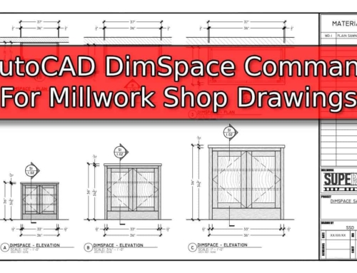
Because of this, we have built our internal drafting standards in such a way that dimensions first call out the individual part, then the sub-assembly, and finally the overall. We also utilize the DimSpace Command to ensure that our dimensions are consistent as well as visually appealing.

Have our Multi-Leader Standards been applied Properly?
As I mentioned in the previous section, I am very finicky about how our Dimensions and Multi-Leaders are situated. I personally find that Multi-Leaders which cross over Dimension Lines are difficult to read. I also take issue with Multi-Leaders that contain a half-dozen arrows pointing to various items.
In an effort to minimize crossing lines, our standard is to place Dimensions on one side of the view and Multi-Leaders on the other. This can’t be accomplished in all situations but it creates a foundation that we feel is neat and organized.
Since we’re placing a magnifying glass on my Drafting OCD – we also try to maintain right angles on Multi-Leaders as well as making the landings align.

Does the Room Share a Common Floor?
Views sharing a common floor stems from having strong Millwork Drafting Fundamentals. We like to situate our drawings in such a way that we can easily strike a construction line and see one single floor line in all views. By doing this we can easily offset that floor line to ensure that our vertical heights are consistent from one view to the next.
Think of it this way – how many times have you seen Shop Drawings of an L-Shaped Room where the counter in one view is 34″ and 36″ in another. This isn’t typically correct and utilizing a common floor allows you to easily identify this simple error.

Has Vertical and Horizontal Alignment been Applied?
Vertical and Horizontal Alignment circles back to my Drafting OCD. Since we utilize the DimSpace Command for Dimensions and our Multi-Leaders are aligned by landing – it only makes sense that when a Plan View is stacked oven an Elevation View that all Dimensions and Multi-Leaders should align on the sheet.
Some people may feel that this is entirely cosmetic but we feel that it creates a neat and organized drawing which is easy to read.

Has the Correct Hatching been Used?
Here at Superior Shop Drawings, we utilize hatching to show a variety of information. One example of this comes in the form of pattern direction on Plastic Laminate and Wood Veneer. Rather than scattering grain direction markers across an elevation, we prefer to hatch all of the applicable parts.
In addition to the elevation, we also utilize hatching on our sections. This helps to identify material types and clarifies what will wind up being Particle Board as opposed to Plywood or MDF.
Our Internal Drafting Standards stipulate which hatch pattern should be used in which situation. We also have recommended scales and transparencies that are dependent on the scenario.

Is Hardware Consistent?
Most Drafting Departments maintain an active Block Library – Superior Shop Drawings is no different. Anytime we draw up a new piece of hardware, we try to catalog it in such a way that we can easily reuse it as needed on future projects. One potential problem with utilizing a Block Library is that sometimes a hiccup or two can arise if everyone isn’t on the same page.
Lets say, for example, you and a fellow drafter are working on a large hospital project. You both have counters to draw up which utilize Counter Support Brackets. The Architectural Drawings show what looks like Rakks Surface Mounted Bracket – so your partner begins using the Rakks EH1818 Block.
You, on the other hand, noticed that the Scope of Work is calling for A&M Surface Mounted Brackets. Perhaps this was a change made along the way to reduce cost. Regardless of what caused this change – the project now has two very different styles of Support Brackets used under the counters.
We see this type of issue more often when a generic block is used in one area but the actual piece of hardware is used in another. One example of this is a generic Concealed Hinge Block versus a Blum Inline – or a generic Cam Lock versus a Timberline Door Lock.
It is important to look through the Shop Drawings to ensure that the same Hardware Blocks are being used for consistency.

Step 3: Review for Technical Accuracy
The final stage of our Millwork Shop Drawing Review Process is all about Technical Accuracy. This step is where we spend the bulk of our time – by far!
The Technical Review is our check in the system that ensures our customer is being provided with everything they paying for. It also ensures that our drawings are accurate and match both the Architectural Drawings and Project Specifications.
Do the Drawing Match the Scope of Work?
When we provide a potential customer with a Free Quote for Millwork Shop Drawings, it is normally developed from a Scope of Work – which the customer provides. This is essentially a breakdown of what the Cabinet Shop will be supplying for the project.
The first stage of the Technical Review if the most critical – do our Shop Drawings accurately reflect what is outlined in the cope of Work?
- Is the Room / Item Included in the Scope of Work
- Have we detailed all the necessary items within the room?
- Is the Plan / Elevation / Section / Detail count correct?
- Are all excluded items marked “By Others”?

Are the Architectural References Correct?
As described in our Standards Review Section detailing Proper Use of Tags – I noted that our Internal Drafting Standards requires that all Tags include an Architectural Reference. This simple piece of information can be a blessing when correct, as it makes cross referencing the Architectural Drawings a breeze.
If this little piece of information is incorrect, it can be downright maddening!
This check takes a little extra time to perform but it makes everyone’s job easier. Everyone from the Architect / Designer / Homeowner down to each trade can easily cross reference our drawings without having to waste time hunting down specific views in the Construction Drawings. When correct, the Architectural Reference tells them exactly where to look.

Are the Finish Callouts Correct?
Finish Callouts are a major component of all Shop Drawings. These callouts identify the Species, Material, and/or Finish of all items on the drawings. Often times a key is used, such as WD-1 (Wood 1) or PL-1 (Plastic Laminate 1) to simplify things. This saves time during the drafting process but can lead to simple errors if the designations were to get mixed up.
In this portion of the review we want to double check and make sure that all Finish Callouts are correct and match the Project Finish Schedule.
Mixing up the designations can be the difference between ordering several hundred board feet of Plain Sawn White Oak when Rift was specified; or ordering a unit of Wood Grain Laminate when a Solid Color was specified. Both scenarios can be a costly mistake.

Are the Hardware Callouts Correct?
Hardware Callouts are very similar to Finish Callouts in that they utilize a letter or number designation as shorthand for a particular piece of hardware. A Hardware Callout for HDW-1 may represent a Doug Mockett Bar Pull while HDW-2 may represent an Amerock Wire Pull.
Mixing up these designations could lead to a Project Manager or Purchaser placing an order for too much of one item and not enough of another. Even worse, it could make it to the shop floor where doors are drilled for the wrong hardware.
In this portion of the review we want to make sure that all Hardware Callouts are accurate and match the Project Hardware Schedule.

Has Grain Hatching been Applied?
In the Drafting Standards portion of the Review Process, I outlined a check to ensure that correct hatching was used. As outlined in that section, we prefer to skip the use of scattered Grain Direction Markers. Instead, out Internal Drafting Standards call for the use of hatching on all parts that have a pattern direction.
In addition to being a cleaner presentation, this allows us to show the pattern direction on every part in the view. This check ensures that the hatching has been applied to all applicable parts and that the pattern direction is correct.

Do the Shop Drawings Match Customer Construction Methods?
When you are in a line of work such as ours – providing Outsource Millwork Shop Drawings, you get the opportunity to see a wide range of Constructions Methods. We may produce Shop Drawings for one company that produces something one way and the next company may do something wildly different.
This variation in construction methods makes my job interesting. I enjoy learning new ways of engineering Millwork and the change of scenery from one job to the next presents me with new challenges. These challenges keep me on my toes and allow to grow as a Draftsman.
Most In-House Drafting Departments will not need to concern themselves with varying construction methods but it is something we deal with here at Superior Shop Drawings on a daily basis. This check in the system ensures that our Shop Drawings accurately depict the construction methods that our customers use for manufacturing.

Develop Your Own Shop Drawing Review Process
While the process we have outlined above may seem extensive – it really isn’t much different from what you would find in any Architectural Millwork or Custom Cabinet Shop across the country. When the time comes for you to Review Millwork Shop Drawings, take your time and be thorough.
Rest assured that the extra time spent during your review process will pay for itself when the Final Drawings are released to the customer – be it a Homeowner, Designer, or Architect.
When everyone is on the same page there is less frustration and less time is wasted on rework.
No matter who is doing the drafting here at Superior Shop Drawings – be it myself, Steve, or someone on our drafting team, our review process never changes. It is critical to develop a system that is clear so that all parties involved know what is expected of them and can plan for success. If you follow the steps outlined above, you will have created a set of Quality Shop Drawings.
This simple position allowed him to get his proverbial foot in the door and choose Cabinetmaking as a Career path in High School.
With more than twenty years of combined experience as both a Cabinetmaker and Draftsman - Walt uses his experience to Engineer and Produce Millwork Shop Drawings.
- Millwork Shop Drawings: Training Survey - May 5, 2024
- Optimize Your Shop Drawings: Exploring the Power of theAutoCAD DimSpace Command - December 5, 2023
- The 4 Grades of Kitchen Cabinets: What Does It All Mean? - November 28, 2023

