
Over the past few months, Stephen and I have been making an effort to produce Blog Content that does a good job of anticipating and answering questions from Potential Superior Shop Drawings Customers.
In this article, we want to go beyond the basic questions – such as How Much do Millwork Shop Drawings Cost? and How Long Does it take to Produce Shop Drawings, and take a deeper look at what is involved in Creating Quality Shop Drawings.
The goal of this article is to be more than just a resource for our potential customers – we want anyone from our industry to take something away from this writing.
What Are Shop Drawings?
Before we can dive into how to actually generate a set of Shop Drawings, we first need to identify what makes them different from other types of construction documents.
In our industry, everything starts with the Architectural Drawings. There are several phases of drawings issued along the way but the most important is the IFC Set (Issued for Construction).
The IFC Drawings will have the design intent finalized and most of the construction issues worked out. Once the Architect has released the Construction Drawings, the various trades involved with the project can began creating their own versions of Shop Drawings
In the case of Superior Shop Drawings, our specialty is creating Millwork Shop Drawings. These are drawings that will be used by the Millwork Supplier and/or Cabinet Shop to construct the product they were contracted to provide.
Other trades will have their own versions of Shop Drawings. Since our field focuses on the cabinets, that is where the focus of this article will remain.
So to summarize, Shop Drawings tend to focus less on the design intent and instead put emphasis on how the final product will be manufactured.
Project Specifications
Now that we know what makes Shop Drawings different from Architectural IFC Drawings, we need to find a place to begin. In my experience, the first thing that I like to look over before I start drawing is the Project Specifications.
Most Architects will release a Project Specification Manual in conjunction with their Construction Drawings. This manual will be sorted by Division and will spell out the standards of the building.
For example, when we are given a project to produce Shop Drawings, we begin looking over the Division 06 Specifications – which includes Wood, Plastic, and Composites.
By navigating to the Architectural Woodwork Sub-Section (Division 064000), we can gather information that may not be included on the Architectural Drawings. We can then take this information and cross reference it with the Architectural Drawings and the Project Scope of Work.

Request For Information
When a project is awarded to Superior Shop Drawings – we like to cross reference the Architectural Drawings and Project Specification Manual and compare them to the Project Scope of Work.
The Scope of Work is a document that our customer (The Architectural Millwork Supplier and/or Cabinet Shop) provides us that breaks out what it is that they will be providing.
If there is a conflict between any of these documents, it is important that we call attention to it in the form of a Request for Information (RFI). This RFI is sent to our customer who will either respond to it or move it up the chain to the General Contractor.
A common example of this type of conflict occurs in hardware selection. For instance, the Architectural Drawings may call out “Counter Support Brackets”, the Scope of Work may call for A&M Hardware Steel Support Brackets, and the Project Specifications Manual may call for Rakks EH1818 Aluminum Surface Mounted Support Brackets.
While both products achieve the same goal of supporting the counter top – the appearance, materials, and cost are very different. On a large project that may include upwards of one hundred support brackets, the impact or project cost could be substantial.
It is critical that this conflict be addressed so that a determination can be made on a possible substitution. Once that determination has been reached, the Shop Drawings should reflect the decision and call out the proper piece of hardware.

Creating Shop Drawings
With the initial project questions issued in the form of an RFI, we can now begin working on our Shop Drawings. It is important to know that there is no Standard Format and the look and feel can vary greatly from one Draftsman to the next.
Here at Superior Shop Drawings, we have our own set of Drafting Standards. These internal standards were created to ensure consistency throughout the project. By creating consistency, not only do the drawings look clean, we find it easier to pick up on errors.
The following sections will focus on the Internal Drafting Standards of Superior Shop Drawings.
Plan View Drawings
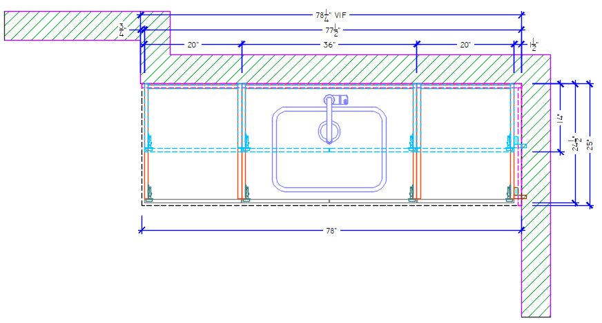
Generally speaking, Plan Views depicted on Architectural Construction Drawings will be shown from approximately 36 inches above the Finish Floor. This means that Counter Tops and Splash is normally shown as a Solid Line with the Cabinets above and below the counter shown as Dashed Lines.
Our standard practice is to reduce the height of the Plan View to approximately 24″ above the Finished Floor. This allows us to provide more detail on the items that are generally more important – such as the cabinets.
Our Plan View Drawings will show the Case Sides, Hinges, Doors and/or Drawers, Gapping, Fillers, and how they all work in conjunction with one another.
We provide dimensions on the components, sub-assembly, and overall assembly. Wall to Wall dimensions will include a Verify In Field (VIF) note to indicate that sizes may change based on Field Conditions.
Elevation View Drawings
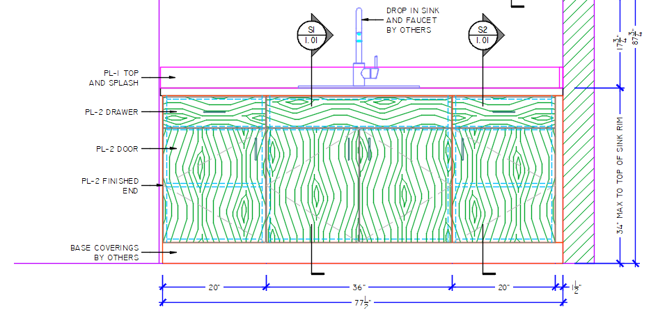
Elevation View Drawings are generally shown as if you were standing directly in front of the item. This view is important to depict cabinet configuration and finish callouts.
Our standard is to project the same level of detail down from the plan. This allows us to show Door and Drawer Gapping while also showing critical components beyond the view – such as case parts and adjustable shelves.
Rather than clutter the drawings with Grain Direction Markers, we prefer to hatch all components that contain grain or a directional pattern. Door Swing and Applicable Hardware is also included in the Elevation.
Section View Drawings
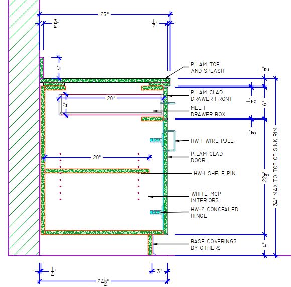
Section View Drawings are one of the most critical aspects of producing Quality Shop Drawings. This is the view that outlines cabinet construction, counter top construction, and shows gapping between the components.
In the example drawing below, we can see that this particular manufacturer utilizes a butt joint at the cabinet back and will staple a 3/4″ panel to the case sides, floor, and rear stretcher.
Their Top Gap is consistently 1/4″ with 1/8″ gaps between doors and drawer fronts. Adjustable shelves utilize 5mm Line Boring and are held back from the hinge boring.
Plastic Laminate Counter Tops are made with a build-up at the front and back to achieve a 1-1/2″ overall thickness. The rear build-up is pulled forward 3/4″ to make on-site scribing easier.
Our standard practice is to not call out specific laminate colors on our Section Views. We do this to reduce the number of Unique Sections required for the project – which in turn reduces the cost for the customer.
Detail View Drawings
Detail View Drawings are typically depicted at a significantly larger scale than Sections. These drawings are produced to call attention to the minor details required in producing a given component.
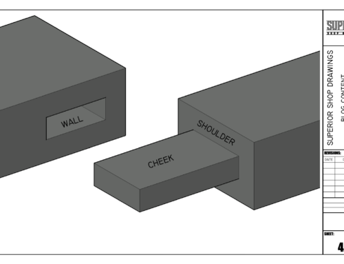
In the example below, we have a Mitered Walnut Column with a Light Box on either side. The column is attached with a concealed wall cleat.
Our internal drafting standards call for details to be drawn at a minimum of 3″ = 1′-0″ (Double the scale of a typical Section View). If space allows, we prefer to shown details at Full Scale.
Like sections, we hatch components to match the materials being used. In this case, the Walnut Column is made out of 3/4″ Solid Wood.

Submittal Shop Drawings
When all shop drawings are completed, they are now considered to be Submittal Drawings. These drawings are sent to the General Contractor for Review and Comment. If the drawings meet the approval of the General Contractor, they are then sent to the Architect for Final Review.
When the Architect is finished reviewing the drawings, they will be returned to the Manufacturer as Approved, Approved as Noted, Revise and Resubmit, or Rejected. The notation from the Architect will determine the next course of action.
Approved
In a best case scenario, Shop Drawings will be returned from the Architect with an Approved Stamp on the cover. While this is the desired outcome, it is not typical.
It is important to understand that in many cases, there is a lot going on with the average project. Between the General Contractor adjusting for Field Conditions and Architect updating Drawings and Documentation – there are a lot of balls in the air.
Throw a Building Owner into the mix that is requesting a modification and it can be very difficult to get all of the bits of updated information to all the right people. For this reason, it can be very difficult to produce Shop Drawings that do not require some kind of notation from the Architect.

Approved As Noted
Approved as Noted is the most common Stamp that you will find on a reviewed set of Shop Drawings. This means that the Architect has verified that the Design of the Millwork Matches his Intent and that the Construction Methods are acceptable.
This set of drawings will include comments and/or instructions (In Red Ink) that are to be followed when the manufacturing process begins.

Revise and Resubmit
The Revise and Resubmit Stamp is typically used when the Architect feels something has been Overlooked, Done Incorrectly, or Substituted without Approval.
In an effort to ensure that moderate errors have been corrected, the Architect wants to see the changes reflected in the Shop Drawings before giving Final Approval.
Under normal circumstances, the Revise and Resubmit Stamp should not be taken personally. While no one likes making redline corrections to drawings, the Architect is simply trying to ensure that the Client is getting what they are paying for.

Rejected
When Shop Drawings come back Rejected, it means that a serious problem has occurred. In most circumstances one of two things have happened. Either a change has occurred and the updated information has not been provided to the Draftsman or significant changes have been made without the approval of the Architect.
Rejected drawings tend to come in two varieties. One includes markups pointing out what is wrong and includes updated documentation showing when the change occurred. The other is a complete rejection with a note that the drawings have not been reviewed due to excessive errors.
When Shop Drawings have been Rejected, the immediate course of action must be to communicate and resolve the issue. Not correcting the problem quickly could lead to parts of the project falling behind schedule.

As-Built Shop Drawings
Once Shop Drawings have met the approval of the Architect, the final phase of drawing can begin.
At this point, a representative of the Millwork Supplier and/or Custom Cabinet Shop will travel to the Project Location and check on site conditions.
Any VIF Dimensions will be checked and accurate dimensions will be provided. In addition, dimensions to Plumbing Center will be recorded as will notations for any potential obstacles.
When all of this information has been transferred and drawings updated – the drawings now become As-Built Shop Drawings. These are considered to be final and should reflect exactly how the product has been manufactured based on Verified Field Conditions.
Some Architects and General Contractors will require that As-Built Shop Drawings be Submitted for Record.
Congratulations, the project is complete and you have provided a set of Quality Shop Drawings. With any luck, all parties involved will be pleased with the quality of work and your company will be given the opportunity to work on future projects.
This simple position allowed him to get his proverbial foot in the door and choose Cabinetmaking as a Career path in High School.
With more than twenty years of combined experience as both a Cabinetmaker and Draftsman - Walt uses his experience to Engineer and Produce Millwork Shop Drawings.
- Millwork Shop Drawings: Training Survey - May 5, 2024
- Optimize Your Shop Drawings: Exploring the Power of theAutoCAD DimSpace Command - December 5, 2023
- The 4 Grades of Kitchen Cabinets: What Does It All Mean? - November 28, 2023


