
About fifteen years ago, I was working in a small Custom Cabinet Shop here in Pennsylvania. Because it was a small operation, the shop did not have any automation. You had to be versatile in order to work there. We had to be able to perform a variety of tasks from the initial lumber selection all the way through to installing the finished product in the customer’s home.
One of the aspects of that business that fascinated me was the transfer of information from the Office to the Production Floor. You see, the owner had been in business for a number of years. He had been drawing everything by hand. The Cabinet Shop is where he spent his days working; his evenings were spent Drafting and Designing.
When it was time to begin working on a given project, we would be given a sheet of 18×24 vellum with hand-drawn Plans, Elevations, and Sections. We tweaked things along the way to scratch in an extra line or scribble some notes across the sheet. It was terribly inefficient and at times maddening trying to make sense of the scribbles.
Being a much younger man back then, I had big aspirations of one day opening up my own Custom Cabinet Shop. I told myself that when the time came, I would have the ability to use AutoCAD and save loads of time. Eventually, I signed up for Night Classes in Architectural Drafting and Design.
Our first class was one that I’ll never forget. The instructor handed us a pouch of supplies and we sat down at a drafting table. He spent the next several hours introducing us to our various instruments and how they would be used to draft on vellum. We spent an entire semester in front of those drafting tables learning fundamentals. I feel strongly that those first few months laid the foundation for me to later excel as a Draftsman.
Often times, when I speak with new Drafters they describe a learning process that was very different than mine. The trend seems to be to skip the drafting table and go directly to the computer. While in and of itself this isn’t a problem, they seem to miss out on learning the process of setting up and how to reduce simple errors.
As you may already know, Superior Shop Drawings specializes in producing Shop Drawings for Architectural Millwork and Custom Cabinets. I would like to walk you through how I apply the fundamentals to drafting up a simple base cabinet.
Common Issue
When it comes to producing Shop Drawings for Architectural Millwork – the most common issue that I see with new Drafters is that they treat each view as if it were completely independent from the others.
For example, they look at the Plan View on the Architectural Drawings and reproduce it. They then set that view aside and turn to the Elevation View and do the same thing. The process is repeated once again to produce the Section View.
Unless the drawings are cross-checked against one another, discrepancies could arise. This is where you can wind up pouring time into a project chasing down easily avoidable errors.
Plan View Drafting Fundamentals
I was taught that the Plan View is your foundation. No matter how simple or complex your drawing needs to be, the Plan is where it all starts. For this example, I’m going to draw up a Base Cabinet with a Counter Top.
I like to begin by drawing up my Architectural Walls. I’ll do this by using Polylines with Ortho On so that I get straight lines and square corners. In this particular example I have a 36″ wide niche that is 30″ deep.
When my Walls are in place, I’ll use the Rectangle Command to produce a 36″ Wide by 25″ Deep Counter Top. After that I’ll add 3/4″ Back and Side Splashes ontop of the Counter.
With the main focus of the view drawn, I’ll now move on to adding in the hidden items below the counter top. This will include a 33″ Wide by 24″ Deep Cabinet and 1-1/2″ Fillers on either side.
To finish up my Plan View, I’ll add Dimensions, Notes, Tags, and Markers.

Elevation View Drafting Fundamentals
I do not jump ahead and simply draw the same items I outlined above. Instead, I’m going to spend a little time to create a check in the system. I’ll do this by striking vertical construction lines from my Plan View to locate the Architectural Walls in my Elevation.
I’ll then use these lines to draw my Architectural Walls directly below my Plan View. I will then create my floor by striking a horizontal construction line. This ensures that when I begin creating my Elevation View that it directly corresponds with the Plan View that I have already completed.
I can now begin offsetting my Floor Line to set my Kick Height (4″ in this case) and my Counter Top Height (34″ Above the Finished Floor and 1-1/2″ Thick). When my height offsets are complete, I’ll strike additional vertical construction lines from my Plan View to locate my Cabinet, Fillers, and Splash.
When all of my offsets are complete, I can begin drawing each item using the construction lines as a guide. This ensures that my Plan and Elevation match one another.
To finish up my Elevation View, I’ll add Dimensions, Leaders, Tags, and Markers.

Section View Drafting Fundamentals
When it is time to begin drafting our Section View, we need to make a slight tweak to the process to ensure that our Plan, Elevation, and Section all match one another. To do this, I like to copy my Plan View and place it off to the side. I then strike a vertical construction line through my plan approximately where my Section Marker is placed on the Elevation.
I then use my vertical construction line to trim away anything on the Plan that is not needed for my Section. Once trimmed, I rotate the copied Plan by 90 Degrees and move it next to my existing Plan.
I can now repeat the same process in which I drafted my Elevation by striking construction lines. I’ll use vertical construction lines from my trimmed Plan View to locate Depths. I’ll then use horizontal construction lines from my Elevation View to locate Heights.
With all of my reference lines in place, I can begin drawing my cabinet components. I’ll then finish the view by adding in Dimensions, Leaders, Tags, and Markers.

Completed Shop Drawing
Now that our Plan, Elevation, and Section have all been drawn – the only thing left to do is erase our reference lines and trimmed Plan View.
By adding in a few extra steps and using Basic Drafting Fundamentals, we drastically reduce the odds of our drawings not matching one another. Our drawings are neat and organized. We have them situated in a way that makes it easy for us to come back later and adjust for Field Dimensions

This simple position allowed him to get his proverbial foot in the door and choose Cabinetmaking as a Career path in High School.
With more than twenty years of combined experience as both a Cabinetmaker and Draftsman - Walt uses his experience to Engineer and Produce Millwork Shop Drawings.
- Millwork Shop Drawings: Training Survey - May 5, 2024
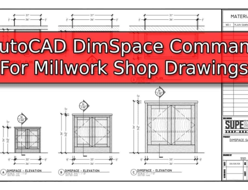
- Optimize Your Shop Drawings: Exploring the Power of theAutoCAD DimSpace Command - December 5, 2023
- The 4 Grades of Kitchen Cabinets: What Does It All Mean? - November 28, 2023

