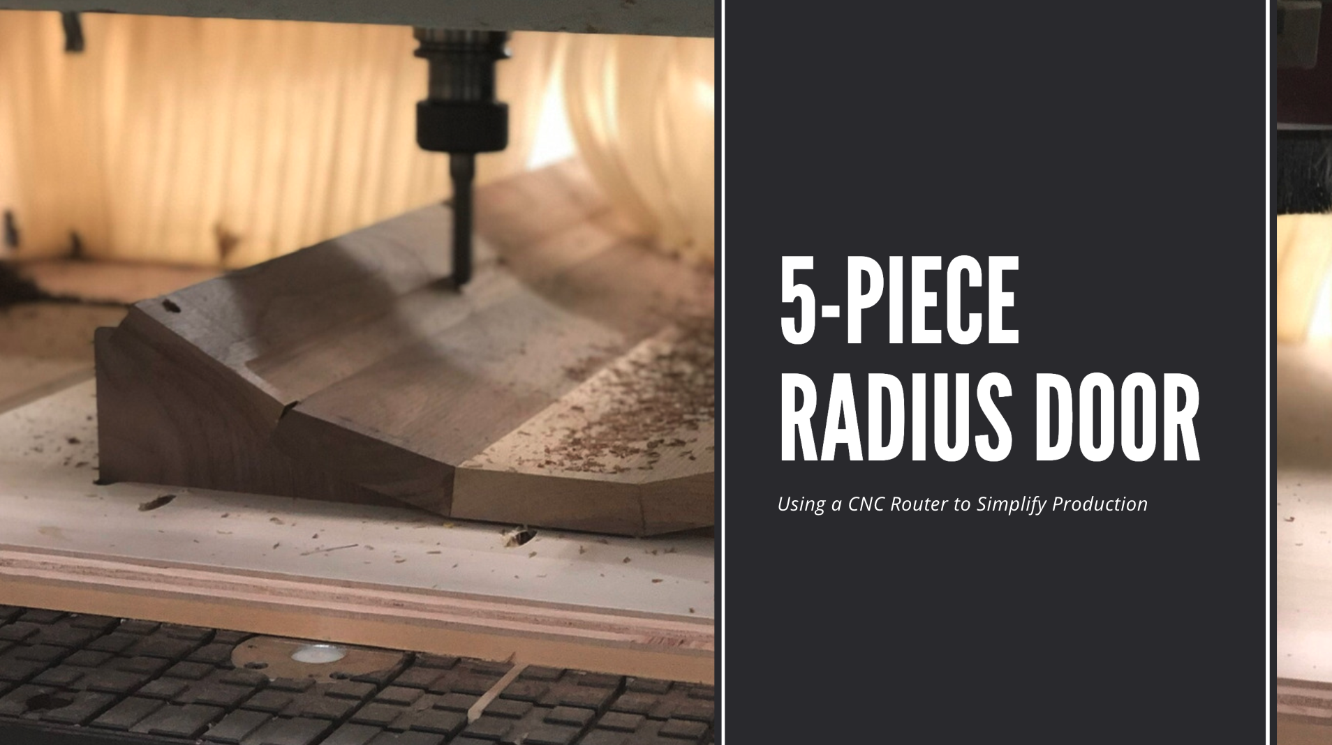
When you spend the bulk of your career doing Custom Cabinet Work for the Residential Market – it presents a unique set of challenges. Of those challenges, there has been one that seemed quite intimidating when I first encountered it. It was a curved cabinet with a 5-Piece Radius Door.
Over the past decade I have engineered a number of these custom doors with great success. In this Blog Post we will walk through my process of using Coppered Construction and a CNC Router to simplify construction.
It is worth noting that there are several scenarios where this process is not necessary. For instance, If your 5-Piece Radius Door includes a flat panel or the a painted finish then it could be made with the use of bendable (kerfed) MDF or cut out of a giant slab of MDF. If, however, you’re making a raised panel door out of solid lumber for a high-end residential kitchen, then making a coopered panel with this process becomes necessary. Be warned that this is a very time intensive process.
Machining a 5-Piece Radius Door on a CNC requires an accurate Plan Section. This is often done in AutoCAD and will be the foundation for all steps moving forward. I can not stress this enough – make sure the door is accurately drawn! Once the Plan Section is complete, we will need to create a jig that will help with glue-up, cradle the part during machine, and can act as a guide for shaping the raised panel.
CAD – Laying out the plan view

The 1st step in the process of making a 5-Piece Radius Door is to get the plan view for the door worked out. Take your time with this step to get everything correct. Everything will be built upon this drawing. An error at this step, depending how big, could require starting over from the beginning. If you haven’t read our post on The Importance of Shop Drawings, please check it out.
Draw your door profile and make sure all dimensions are on the radius. For example, if your door has 2-1/2″ stiles, make sure this is Included in the overall arc length. Once you have the panel drawn to the correct size – Add 1″ to each edge. This will be for fastening the panel to the jigs During CNC Machining. This also avoids having any screw holes in your work. While some of the holes may be hidden in the stile & rail slots, I always find it better to have more material than not enough in something as time intensive as this. I like to print out a 1:1 template so that I can quickly see that the size and angles are correct.

Figure out how many pieces the panel should be split into to make up the radius. Less is better here but it depends on how tight the radius is and the material thickness you wish to use. I like to have the finished panel come off of the CNC 1/16″ heavy. This allows 1/32″ of material to be sanded off of each face to remove the tooling marks. If my finished panel is 3/4″, I want it to come off the machine at 13/16″.
Be sure that when dividing up the pieces that make up the panel, they are all identical in size. This saves time as each piece is machined exactly the same.

Now build your jigs to hold the panel in place on the CNC. I like to have my ribs holding the panel go to the bed of the CNC. This avoids any issues due to material thickness of the base plate holding the ribs. The jigs are usually cut out of shop grade plywood and the thickness of this material can vary. Another tip, (see photo above) use masking tape on the ribs where it contacts the panel. This will help avoid the panel getting glued into place.

For the template that will hold the ribs in place, I like to oversize it roughly 5-6″ from the rib slots. While the dimension is not critical, cutting this out symmetrically will allow this to to be machined from both directions on the CNC. This helps due to limitations on the CNC being used here (more on this below). This also allows the CNC operator to load this onto the machine without the possibility of loading the part upside down.

I cut the “I” shape into the base template holding the ribs. This is to avoid having to square off any corners – see image above.
CAM – Machining

Screw the panel down to the ribs in the 1″ excess that was left on the material. Even if the panel is stuck (glued) to the ribs. The panel may still move on the machine and should be fastened with screws. Make sure to countersink the screws deep enough to not come into contact with the tooling.

Be sure you know the limitations of your CNC. This process requires a good bit of clearance in the “Z” direction. The machine that this program was written for has a drill bank near the tool. This could collide with he material while traveling the full width of the panel face. I have the program go just past half way and then spin the part. This is why the jig is symmetrical.
Now run the back of the panel in the same method. On this CNC being used here the drill bank doesn’t get in the way while running the back. So it can be machined in one pass. I am also using a bit (52-397B) with a cutting depth of almost 3″ to help avoid in any collisions.

Now that the panel is roughed out. Trim the excess 1″ off of the door down to final size and profile the panel. It should be sanded to final thickness before running the profile on the edges of the panel.

You can use the same jigs that were created for machining the coopered panel on CNC to hold the panel in the correct position where it meets the cutter as shown below. In this case, the cutter needs to be flipped and the feed direction reversed.

Now that the panel is complete, let’s talk about making the rails for the door. The rails can be cut out on the CNC as well. I try to fit a few together to save on lumber to cut down on the material waste. The size of the rails and lumber dimensions I have to work with determine how many rails I decide to group together. In this case I decided to group four together, enough for two doors. Because of the tight radius on these doors there will be a lot of end grain showing on the face of the rails. I decided to use some of the sap wood for the core of the rails and veneer the face.

The stiles and rails can be machined with the same method you would use for any other door. My preferred method is to use mortise and tenon jointery.
I hope this article helps with any questions that you have on creating a five piece door with the help of a CNC. If you are new to making radius doors or programming them on a CNC, please leave a comment below or reach out to us so we can help.
- The benefits of an organized kitchen - July 6, 2020
- Popular Kitchen Cabinet Colors of 2020 - July 3, 2020
- The History of Kitchen Cabinets - June 29, 2020
